EN
 AR
 BG
 HR
 CS
 NL
 FI
 FR
 DE
 EL
 HI
 IT
 JA
 KO
 NO
 PL
 PT
 RO
 RU
 ES
 TL
 IW
 ID
 VI
 HU
 TH
 TR
 FA
 MS
 UR
 HA
 JW
 LA
 MY
 KK
 TG
 UZ
 AM
 PS

EIA Coaxial Connector
The EIA (Electronics Industries Alliance) coaxial connector is not a single model, but a series of flange-mounted interfaces standardized for high-power RF transmission (e.g., EIA 50Ω series). Unlike common threaded or bayonet connectors, EIA connectors utilize precision flange mating with bolted fastening, engineered specifically for kilowatt to megawatt-level power applications in broadcast transmitters, radar systems, and industrial heating. Its core advantages include ultra-low insertion loss, superior heat dissipation, and long-term high-power stability, making it the irreplaceable "backbone" interface for high-power RF systems.
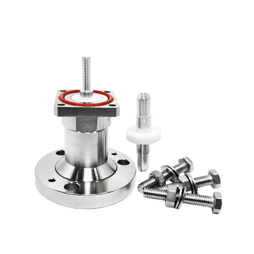
Key Technical Specifications (EIA 50Ω Series Reference)
|
Parameter |
Typical Specification Range |
|
Impedance |
50 Ω |
|
Frequency Range |
DC – 3 GHz (Size-dependent) |
|
Peak Power Capacity |
10 kW – 2 MW+ (Model/cooling dependent) |
|
Average Power Capacity |
1 kW – 500 kW (With forced air/liquid cooling) |
|
Insertion Loss |
<0.05 dB @ 1 GHz |
|
VSWR |
≤1.05 |
|
Coupling Mechanism |
Flange Bolted (4/6/8-hole) |
|
Operating Temperature |
-55°C to +165°C (Cooling required for continuous high power) |
|
Standards Compliance |
EIA RS-358, MIL-F-39012 |
Critical Note: EIA connector size designations (e.g., EIA 1-5/8", EIA 3-1/8") directly correspond to the outer diameter in inches; larger sizes support higher power capacities. Selection must match the transmitter output port and feedline system specifications – cross-size adaptation is strictly prohibited.
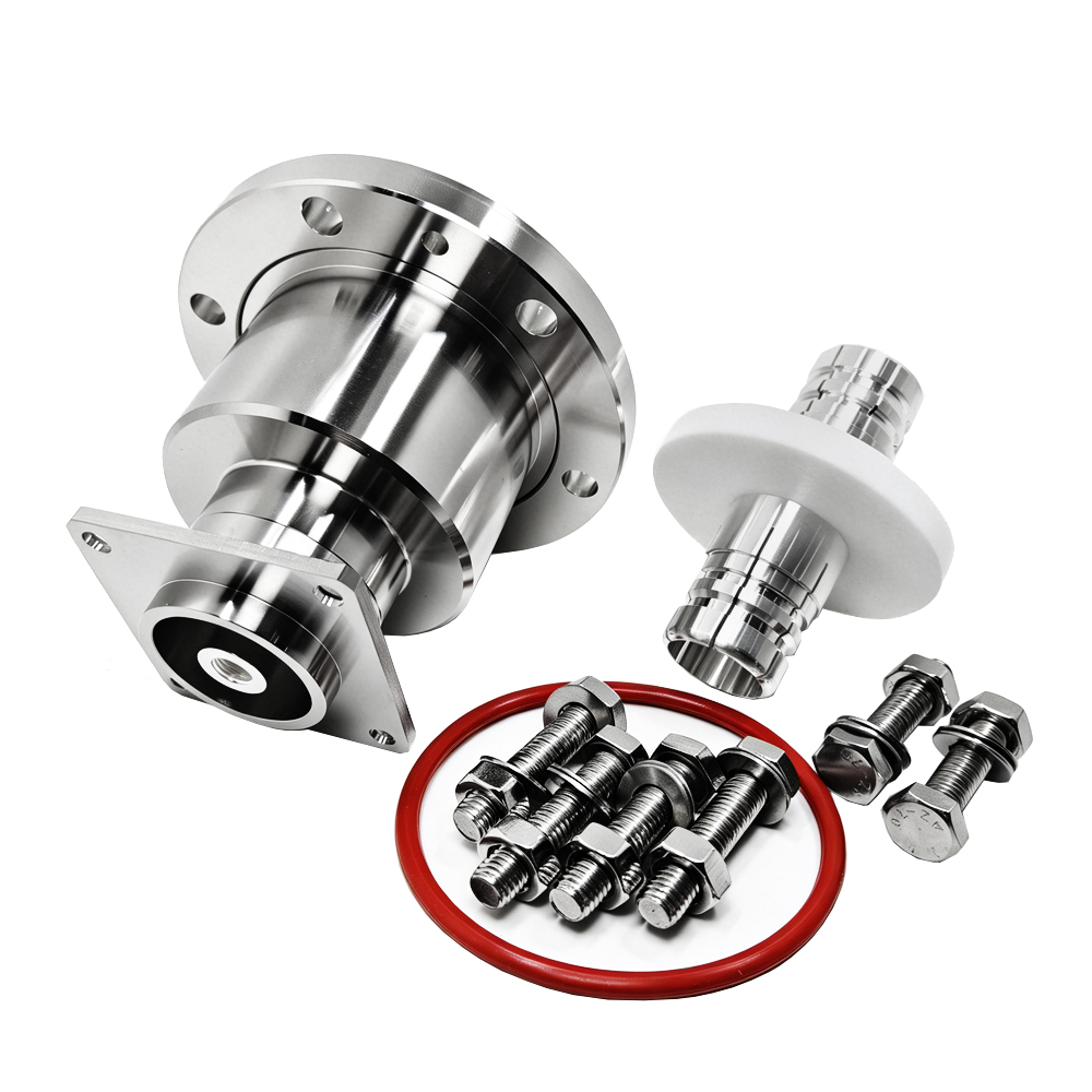
Primary Applications
- Broadcast Transmission: FM/VHF/UHF solid-state/tube transmitter outputs, combiner/splitter interfaces, antenna feedline backbone connections.
- Radar & Communication Base Stations: Long-range early warning radar TR module feeds, satellite earth station HPA outputs, microwave relay high-power amplifier links.
- Industrial RF Heating: Magnetron outputs for plastic welding/wood drying equipment, semiconductor wafer annealing chamber feeds, medical hyperthermia device power transmission.
- Particle Accelerators: RFQ/DTL cavity couplers, klystron window transitions, high-power beam diagnostic probes.
- Test & Measurement: High-power signal generator outputs, directional coupler calibration ports, antenna near-field scan probe feeds.
- Defense Electronic Warfare: Jammer power amplifier array combining, towed decoy transmitter units, shipboard high-power communication systems.
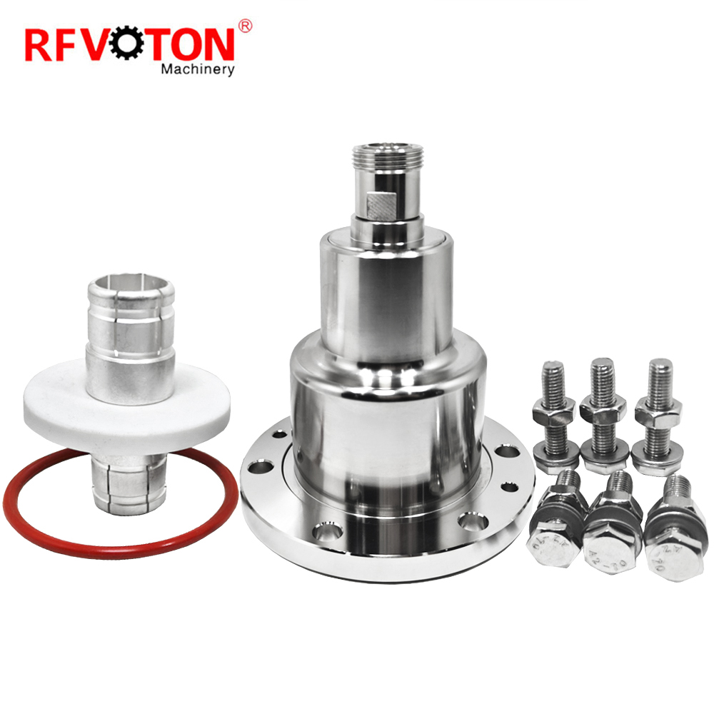
EIA vs. Other High-Power Connectors: Quick Reference
|
Connector Type |
Peak Power |
Coupling Mechanism |
Best Use Case |
|
N-Type |
~1 kW |
Threaded |
Low-to-medium power general purpose |
|
7/16 DIN |
~3 kW |
Threaded |
Base stations / medium power |
|
EIA Flange |
10 kW – 2 MW+ |
Flange Bolted |
High-power backbone / transmitters |
|
LC-Type |
~5 kW |
Bayonet |
Aerospace / compact high-power |
|
Waveguide Flange |
>5 MW |
Bolted |
Millimeter-wave / ultra-high power |
Safety & Maintenance Warnings
- Never mate/unmate under load: EIA connectors have no arc-proof or shock-proof design; always de-energize and fully discharge the system before handling.
- Apply torque evenly: Tighten bolts in a cross-pattern sequence to prevent flange misalignment, which can cause arcing or seal failure.
- Inspect contact surfaces regularly: Oxidation, scratches, or foreign debris can trigger localized overheating; clean with anhydrous ethanol and lint-free cloth.
- Ensure adequate cooling: Maintain unobstructed airflow or functional liquid cooling during high-power operation; overheating will permanently damage the dielectric.
- Use only OEM gaskets: Replacement seals/conductive gaskets must be specified-grade materials; non-compliant parts may cause arcing or leakage.
Hot News
-
Unlocking the "Precision Eye" of Phased Array Radar: The Ultimate Craftsmanship of Phase-Matched Cable Assemblies
2026-09-04
-
SMC Coaxial Connectors
2026-08-23
-
What is RF coaxial connector? What are the characteristics and applications?
2025-07-01
-
BNC Connector
2024-07-22
-
SMA connector
2024-07-19
-
The difference between BNC connectors and SMA connectors
2024-07-03
-
What are the advantages of anti-interference coaxial cables
2023-12-18
-
Complete Guide to Basic Knowledge of Coaxial Connectors
2023-12-18
-
Why is the anti-interference ability of coaxial cables so strong
2023-12-18